PX4FLOW Optical Flow Camera Board
This article describes how to setup the PX4FLOW (Optical Flow) Sensor which can be used in place of a GPS.
Warning
The PX4FLOW is supported from Copter 3.3 and higher. It is not yet supported in Plane or Rover.
Overview
The PX4FLOW (Optical Flow) Sensor is a specialized high resolution downward pointing camera module and a 3-axis gyro that uses the ground texture and visible features to determine aircraft ground velocity. Although the sensor may be supplied with a built-in Maxbotix LZ-EZ4 sonar to measure height, this has not been reliable enough over a range of surfaces in testing, so its readings are not used. It is recommended to purchase a PX4Flow device without the sonar. Instead a separate Range Finder such as the LightWare SF10b should also be attached to the vehicle.
Warning
To best use this flow sensor you will need to purchase a separate range finder like the LightWare SF10b
Install Drivers (Windows only)
On a Windows machine a “PX4Flow” device should appear in Connection drop-down of the Mission Planner (and the Windows Device Manager), or be automatically recognized by QGroundControl. If it does not you may need to download, unzip and manually install the px4flow windows driver which may in turn require allowing installing unsigned drivers.
Using MissionPlanner
Download and unzip the PX4Flow-KLT firmware (source code here)
Connect the PX4Flow sensor to your computer using a micro USB cable.
Open the Initial Setup, Install Firmware screen, select the COM port and click the “Load custom firmware” link. Select the px4flow-klt-06dec2014.px4 binary you downloaded in Step 1. You may need to unplug and plug back in the sensor to start the upload.
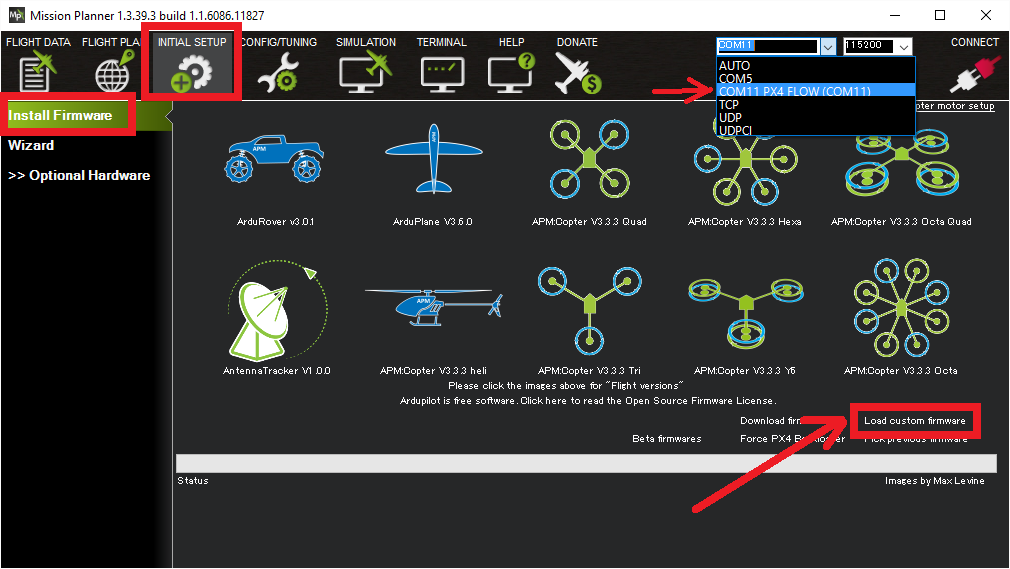
Disconnect and reconnect the sensor/USB cable
Select the appropriate COM port and press Connect
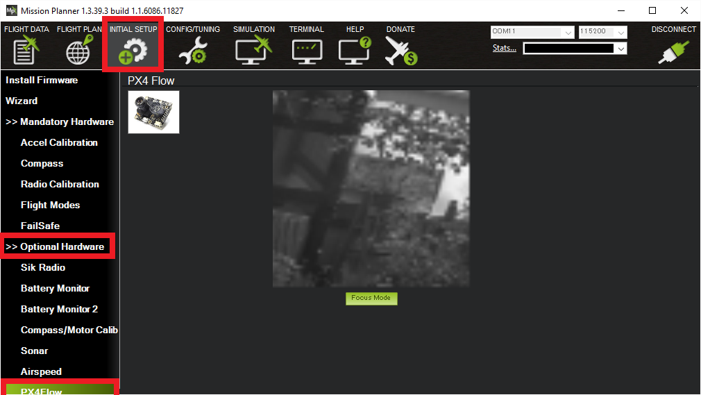
Open the Initial Setup > Optional Hardware > PX4Flow screen
Remove the lens cap and point the camera at a high contrast object at least 3m away. Remove the small screw that stops the lens from turning and adjust the focus until the image appears clearly
Using QGroundControl
In order to use QgroundControl, PX4Flow and ArduPilot, you will need to complete setup and focussing with the firmware loaded by QGroundControl, and then update the firmware to be compatible with ArduPilot.
- Select the Vehicle Setup page, and click the Firmware tab.
- Connect the PX4Flow sensor to your computer using a micro USB cable.
- Check the “Standard Version (stable)” is selected in the ride hand pane. Click “OK”. QGroundControl will flash a firmware that can be used to focus the lens.
- Unplug and replug the sensor. Two extra tabs should appear: “PX4Flow” and “Parameters”.
- Click “PX4Flow”, remove the lens cap and point the camera at a high contrast object at least 3m away. Remove the small screw that stops the lens from turning and adjust the focus until the image appears clearly. This will focus the device to infinity. Refit the screw.
- Download and unzip the PX4Flow-KLT firmware (source code here)
- Unplug the sensor, click on the “Firmware” tab and replug the sensor.
- On the right hand side, click on the firmware version dropdown, and select “Custom firmware file”. Click “OK”. Then select the firmware downloaded above. QGroundControl should now flash a firmware compatible with ArduPilot. QGroundControl will now think that the sensor is a Pixhawk. Dont worry. Unplug it, and connect it to your flight controller.
Connect to the Pixhawk
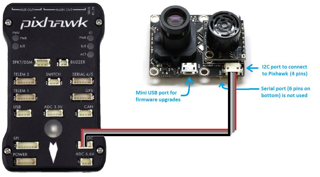
The sensor should be connected to the autopilot via the 4-pin I2C port. In most cases an I2C splitter should be used to allow other I2C devices (like the external RGB LED and GPS/Compass module’s compass) to share the same port.
Mounting to the Frame
The default mounting of the flow sensor is for it to be pointing straight down with the micro USB port pointing towards the front of the vehicle. On the back of the sensor you should see the axis printed, the X axis should point forwards and the Y axis to the right. The FLOW_ORIENT_YAW parameter can be used to account for other yaw orientations.
It is important that the flow sensor be mounted where it does not experience angular angular vibration that could blur the image.
Note
The default mounting orientation is different to that shown on the ETH PX4FLOW wiki. If you mount the board as shown in the ETH PX4FLOW wiki, you will need to set FLOW_ORIENT_YAW to -9000.
Enabling the sensor
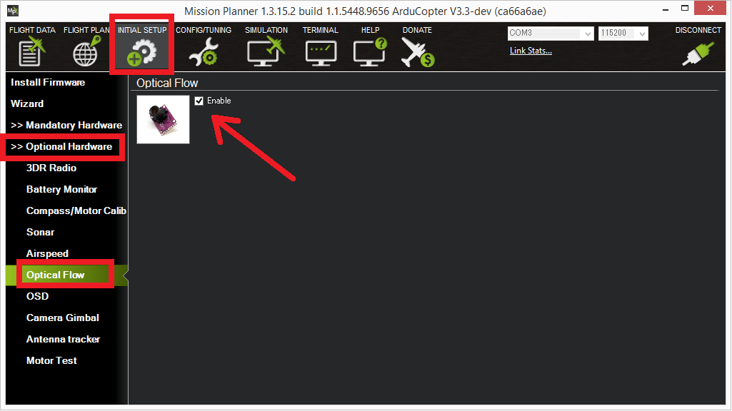
The sensor can be enabled by connecting to the flight controller with the Mission Planner and then on the Initial Setup | Optional Hardware | Optical Flow page check the Enable checkbox. Alternatively the FLOW_ENABLE parameter should be set to “1” through the full parameters list. The sensor will be initialised once the Pixhawk board is rebooted.
Testing the sensor
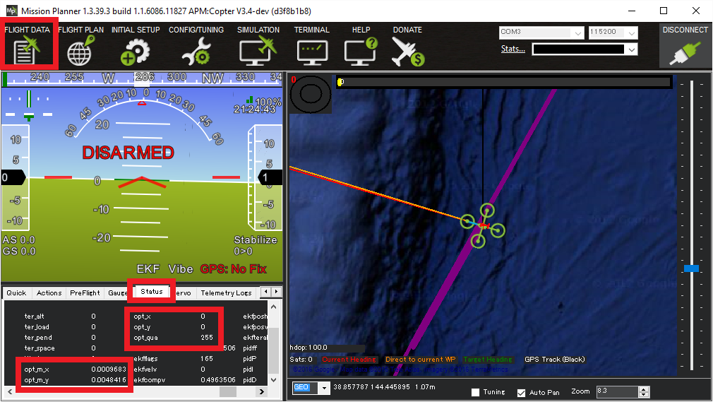
With the sensor connected to the flight controller’s I2C port, connect to the flight controller with the Mission Planner and open the Flight Data screen’s Status tab. If the sensor is operating you should see non-zero opt_m_x, opt_m_y and an opt_qua values.
Calibrating the sensor
Connect to your flight controller and ensure that logging while disarmed is enabled (In Copter-3.3 set LOG_BITMASK to 131071, In Copter-3.4 LOG_DISARMED to 1)
Find a location with a textured surface and good lighting (natural light or strong incandescent)
Remove Propellers (safety first)
Power on the vehicle and hold level away from your body and at eye level
Rotate about the vehicle in roll through a range from -15 to +15 degrees in about a second and then back again. Repeat this 5 to 10 times. By closing one eye you will be able to keep the centre of the sensor stationary against the background while you do the rotation.
Repeat about the vehicle pitch axis.
Download the data flash logs and plot the
OF.flowX,OF.bodyXandIMU.GyrXdata. It should look something like this: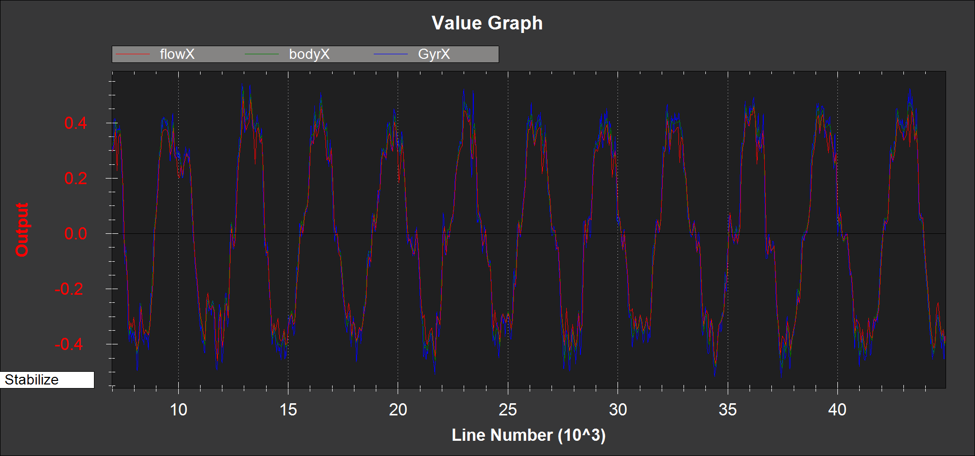
If
OF.flowXis larger or smaller thanOF.bodyX, then it can be adjusted by changing theFLOW_FXSCALERparameterIF
OF.bodyXis uncorrelated or opposite sign toIMU.GyrX, the FLOW_ORIENT_YAW parameter is probably set incorrectly or you do not have the flow sensor pointing downwardsPlot the
OF.flowY,OF.bodyYband,IMU.GyrYdata. It should look something like this: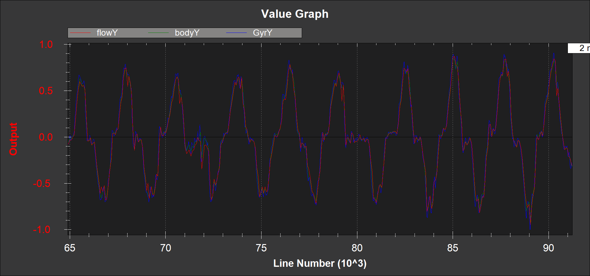
If
OF.flowYis larger or smaller thanOF.bodyY, then it can be adjusted by changing theFLOW_FYSCALERparameterIF
OF.bodyYis uncorrelated or opposite sign toIMU.GyrY, the FLOW_ORIENT_YAW parameter is probably set incorrectly or you do not have the flow sensor pointing downwards
Range Sensor Check
Check the EKF5.meaRng message in the flashlog from your flow sensor calibration test. Check the following:
- There is continuous range measurement.
- It outputs a range on the ground that is 10cm of the expected value (remember that measured range will increase when you roll or pitch the vehicle because the laser is then measuring on a slant)
Pre-Arm checks
To allow arming and taking off in Loiter without a GPS the GPS arming check should be turned off as shown below. Unchecking “All” and “GPS” and leave all other options checked.
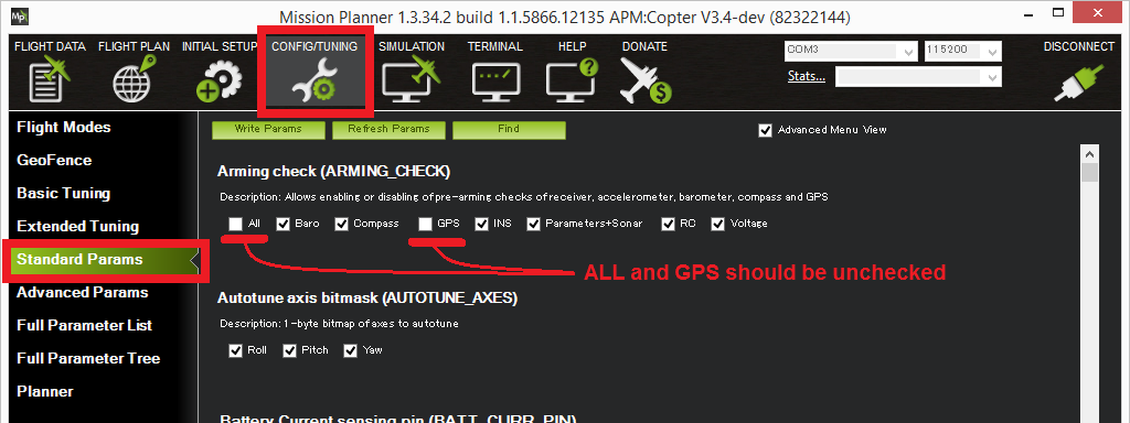
Because optical flow requires good sonar/range finder data when the optical flow is enabled, an additional pre-arm check is enforced.
While the vehicle is disarmed you should lift the vehicle straight up to at least 50cm but no higher than 2m (if the rangefinder sees a distance of over 2m you will need to restart the flight controller).
The error message when arming fails this check is “PreArm: check range finder”
This check can be disabled by unchecking the “Parameter/Sonar” arming check.
First Flight (Copter Only)
- Set EK2_GPS_TYPE = 0 (we don’t want the optical flow being used by the EKF at this stage)
- Perform a short test flight hovering in stabilise or AltHold at small lean angles at heights ranging from 50cm to 3m with
- Download the flash log and plot the following in mission planner
- EKF5.meaRng should correlate with the change in vehicle height
OF.flowXandOF.flowYshould be varyingOF.bodyXandOF.bodyYshould be consistent with IMU.GyrX and IMU.GyrY
Second Flight (Copter only)
Warning
You will need at least 15m of clear space around the vehicle to do this flight safely. If the optical flow velocity estimates are bad, you will have little warning and the copter may lean to it’s maximum lean angle very quickly.
- Set EK2_GPS_TYPE = 3 to make the EKF ignore GPS and use the flow sensor
- Ensure you have Loiter and either AltHold or Stabilize mode available on you transmitter.
- Take-off in loiter and bring the copter to about 1m height
- If the vehicle starts to accelerate away or there is erratic pitch or roll movement, then switch to Stabilise or AltHold and land. You will need to download the log file and share it on the forums to understand why.
- If it holds location then congratulations, you have succeeded and can now start experimenting with height changes and moving it around in LOITER