Advanced Compass Setup
This article provides advanced guidance for how to setup and calibrate the compass (magnetometer).
Tip
Users with who have selected the UBlox GPS + Compass Module (recommended) and have mounted it in the default orientation can usually perform a simple “Onboard Calibration” as described in Compass Calibration).
This topic provides a more complete overview of compass calibration. It will be useful if the compass is mounted in a non-standard orientation or if you need additional calibration support.
Overview
Accurately setting up the compass is critical because it is the primary source of heading information. Without an accurate heading the vehicle will not move in the correct direction in autopilot modes (i.e. AUTO, LOITER, PosHold, RTL, etc). This can lead to circling (aka “toiletbowling”) or fly-aways.
ArduPilot currently allows up to three compasses to be connected. Only
one compass (specified using the COMPASS_PRIMARY parameter) is used
for navigation. While many autopilots have an internal compass, most
will instead use an external compass. This provides more reliable data
than an internal compass because of the separation from other
electronics.
Standard configurations for the main autopilot boards are shown in the table below:
| Configuration | Compass #1 | Compass #2 |
|---|---|---|
| Pixhawk + Compass | External | Internal |
| Pixhawk (no external compass used) | Internal | Available |
| APM2.6 | External | Not supported |
| APM2.5 | Internal | Not supported |
| APM2.5 trace cut, external compass used | External | Not supported |
Most users will only need to select their autopilot/compass configuration and perform the Live Calibration but details are also given on the less-used CompassMot and Manual Declination. Most of this configuration can be performed from the Mission Planner’s Initial Setup | Mandatory Hardware | Compass screen. Other ground stations may have similar features.
Tip
The article is Copter-focused but the instructions are equally applicable to Plane and Rover (except where marked).
Configuration settings
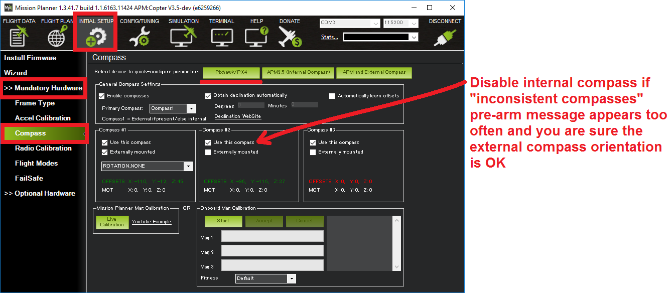
The Mission Planner Compass Setup screen can be found in menu Initial Setup | Mandatory Hardware | Compass in the sidebar. This screen is used for setting almost all compass configuration and tuning parameters.
Quick configuration
Mission Planner supports automatic configuration of almost all parameters for the most common autopilot boards. All you need to do is select the button corresponding to your autopilot controller:
- For most modern flight controller, select the button Pixhawk/PX4. You may be prompted for a specific ArduPilot version.
- For APM 2.6, select APM with External Compass.
If your external compass is in a non-standard orientation, you must manually
select the orientation in the combo box (change from ROTATION_NONE).
When externally connected the COMPASS_ORIENT option operates independently
of the AHRS_ORIENTATION board orientation option.
Most users will then only need to press the Live Calibration button and perform a Live Calibration.
Checking Compass Orientation
- Ensure your AHRS_ORIENT parameter is correct. This will ensure that your internal compass’ orientation will be correct
- When rotating your aircraft through all axes each of the compasses should move in the same direction, and should be of approximately the same values
- Northern Hemisphere: - Z-component should be positive - when pitching the vehicle down, the X component should increase in value - when rolling the vehicle right, the Y component should increase in value
- Southern Hemisphere: - Z-component should be negative - when pitching the vehicle down, the X component should decrease in value - when rolling the vehicle right, the Y component should decrease in value
General settings
The general settings apply to all compasses connected to the autopilot controller:
Enable compasses: determines whether whether (any) compasses are enabled. If enabled the flight controller will use the primary compass for heading data, otherwise the heading will be estimated from GPS. Enabling this checkbox corresponds to setting parameter
MAG_ENABLE=1.Note
- Compasses should always be enabled for Copter/Rover, but may be
disabled (not recommended) for Plane.
Primary Compass: specifies which compass ArduPilot will use for heading data (only one compass is used for navigation). Normally this will be set to the first compass (“Compass1”). This selection list corresponds to setting the parameter
COMPASS_PRIMARYto a value from 0 to 2 (compasses are 0 indexed, even though labelled in the screen from 1 to 3).Obtain declination automatically: sets the declination based on lookup tables following GPS lock. Users can override this default behaviour; after deselecting the checkbox (
COMPASS_AUTODEC=0) they can manually enter declination inCOMPASS_DEC.Automatically learn offsets: TBD.
Compass specific settings
The settings that are specific to each compass are grouped together. Some settings are only visible when the compass is enabled.
Use this compass: This checkbox enables a particular compass for use by the autopilot. Each checkbox corresponds to a
COMPASS_USExparameter (where x is 0 to 2, depending on the compass).Note
- Even if multiple
COMPASS_USExparameters are set to 1, the autopilot will still only uses the primary compass (
COMPASS_PRIMARY).
- Even if multiple
Externally mounted: Set whether or not a particular compass is externally mounted (corresponds to
COMPASS_EXTERNAL=1). If the compass is internal it uses the flight controller’s orientation (AHRS_ORIENTATION). If the compass is external, the orientation may differ from the flight controller (set using the selection list discussed next)Compass orientation: sets the compass orientation for externally mounted compasses. The value is saved as a
COMPASS_ORIENTxparameter.
The OFFSETS (COMPASS_OFFSx) and and MOT (COMPASS_MOT) parameters
are populated by the live calibration and CompasMot procedures (see the
calibration sections below).
Live calibration of offsets
Live calibration calculates offsets to compensate for “hard iron” distortions.
Click the Live Calibration button.
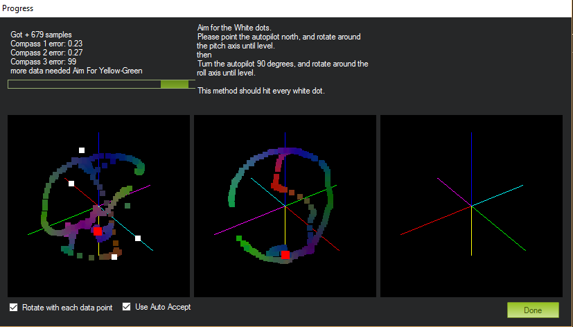
A window should pop-up showing you the state of the live calibration. This shows a sphere for each compass with a red dot showing where the compass is pointing and six “white dot” targets around the sphere. You rotate the vehicle so that the red dot reaches each white dot and causes it to disappear.
As you rotate the vehicle you will notice the red dot moves and (perhaps confusingly) the sphere itself also rotates. A colored trail is left behind wherever the compass has already been: high values (> 400) will turn yellow and may indicate magnetic interference. Offsets > 600 will turn red and generate a warning.
Hold the vehicle in the air and rotate it slowly so that each side (front, back, left, right, top and bottom) points down towards the earth for a few seconds in turn.
The calibration will automatically complete when it has data for all the positions. At this point, another window will pop up telling you that it is saving the newly calculated offsets. These are displayed on the main screen below each associated compass.
Note
- In Copter-3.2.1 and later offsets are considered acceptable
provided their combined “length” is less than 600 (i.e. sqrt(offset_x^2+offset_y^2+offset_Z^2) < 600). Prior to Copter 3.2.1 the recommendation was that the absolute value of each offset be less than 150 (i.e. -150 < offset < 150).
The video below is from earlier versions of the calibration routine but may still produce good offsets.
CompassMot — compensation for interference from the power wires, ESCs and motors
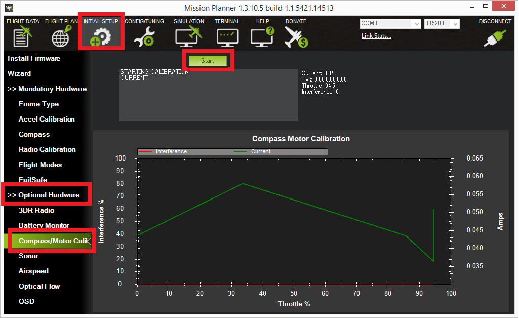
This is recommended for vehicles that have only an internal compass and on vehicles where there is significant interference on the compass from the motors, power wires, etc. CompassMot only works well if you have a battery current monitor because the magnetic interference is linear with current drawn. It is technically possible to set-up CompassMot using throttle but this is not recommended.
Please follow these instructions:
Enable the current monitor (aka Power Module)
Disconnect your props, flip them over and rotate them one position around the frame. In this configuration they should push the copter down into the ground when the throttle is raised
Secure the copter (perhaps with tape) so that it does not move
Turn on your transmitter and keep throttle at zero
Connect your vehicle’s LiPo battery
Connect your flight controller to your computer with the usb cable
If using AC3.2:
You should hear your ESCs arming beep
Raise the throttle slowly to between 50% ~ 75% (the props will spin!) for 5 ~ 10 seconds
Quickly bring the throttle back down to zero
Press the Finish button (AC3.2) or press Enter (AC3.1.5) to complete the calibration
Check the % of interference displayed. If it is less than 30% then your compass interference is acceptable and you should see good Loiter, RTL and AUTO performance. If it is 31% ~ 60% then the interference is in the “grey zone” where it may be ok (some users are fine, some are not). If it is higher than 60% you should try moving your APM/PX further up and away from the sources of interference or consider purchasing an external compass (or GPS+compass module (some of these)).
Here is a video of the procedure based on AC3.1.5:
Manual declination
By default the declination is looked up in a compressed table when the vehicle first achieves GPS lock. This method is accurate to within 1 degree (which should be sufficient) but if you wish to use the uncompressed declination:
Open the Declination Website.
It should automatically figure out your location based on you IP address or you can enter your location
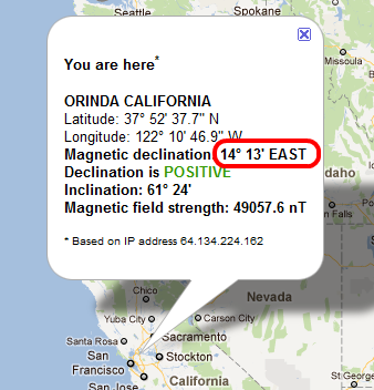
Uncheck the Obtain declination automatically checkbox and manually enter the declination (highlighted in red in the image above) into the mission planner’s declination field. In this example, we would enter “14” Degrees and “13” Minutes.
As soon as your cursor exits the field (i.e by pressing Tab) the value will be converted to decimal radians and saved to the
COMPASS_DECparameter.
Tuning declination in-flight
Although we do not believe this is ever necessary, you can manually tune the declination in flight using the Channel 6 tuning knob on your transmitter by following these steps:
Connect your Pixhawk (or other board) to the Mission Planner
Go to the Software | Copter Pids screen
Set the Ch6 Opt to “Declination”, Min to “0.0” and Max to “3.0”. This will give a tunable range of -30 to +30 degrees. Set Max to “2.0” to tune from -20 to +20 degrees, etc.
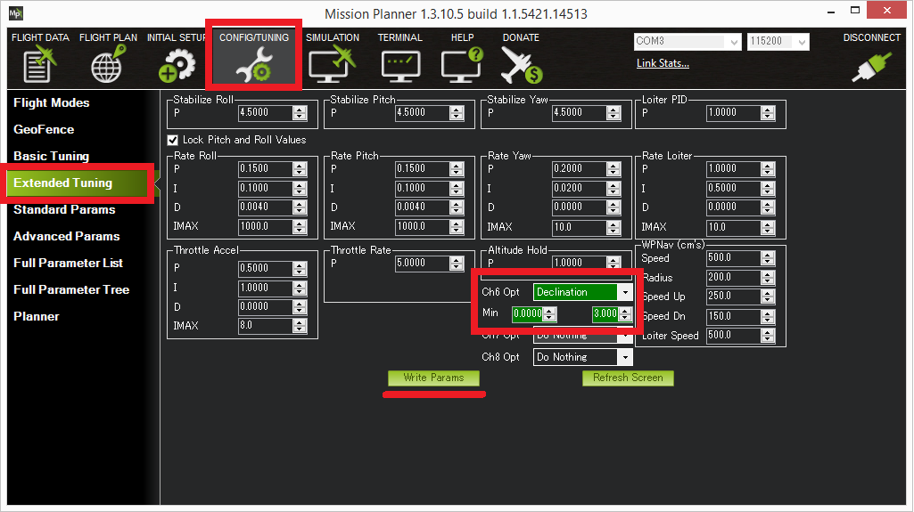
Check the declination is updating correctly when turning the channel 6 tuning knob to it’s maximum position, go to Config/Tuning | Standard Params screen, press the Refresh Params button and ensuring that
COMPASS_DECis 0.523 (this is 30 degrees expressed in radians)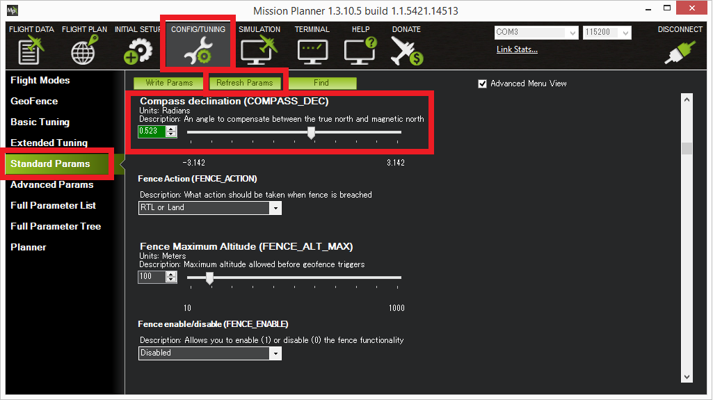
Fly your copter in Loiter mode in at least two directions and ensure that after a fast forward flight you do not see any circling (also known as “toilet bowling”).
If you find it’s impossible to tune away the circling then it’s likely you will require an external compass or GPS+compass module (some of these)
Compass error messages
- Compass Health: The compass has not sent a signal for at least half a second.
- Compass Variance: In the EKF solution, compass heading disagrees with the heading estimate from other inertial sensors. Clicking the EKF button on the Mission Planner HUD will show the magnitude of the error.
- Compass Not Calibrated: The compass needs to be calibrated.
- Compass Offsets High: One of your compass offsets exceeds 600, indicating likely magnetic interference. Check for sources of interference and try calibrating again.
