Camera Gimbal with Servos
This article explains how to connect a camera gimbal with servos to a flight controller and configure it for use with ArduPilot (in Mission Planner).
Overview
Copter, Plane or Rover can stabilize a gimbal with up to three axis of motion using any of the free output channels. Combining stabilization with input from the pilot is also possible (normally using receiver’s channel 6 tuning knob).
The examples shown below use Copter screen shots, but work exactly the same for Plane and Rover.
A camera’s shutter can be triggered from the APM once connected with a servo or “relay”. The act of triggering the shutter can be controlled through your receiver’s channel 7 switch or automatically during missions.
For best performance, ensure that after you add the extra weight of the camera gimbal your copter still hovers ideally at 50% throttle but certainly no more than 70% throttle while in Stabilize mode because an underpowered copter also has less power to recover from disturbances.
Camera mount and build
The camera needs to be mounted securely to the gimbal, but in such a way that reduces/dampens vibrations from the motor. It is difficult to achieve both aims at the same time!
Common methods for mounting the camera on the gimbal include using: soft foam, stiff foam, neoprene tubes (mount camera on tube side), surgical tube, rubber bands, nylon bolt (direct stiff attachment) and velcro. Tubes have been used mostly on traditional helicopters. We make no specific recommendation here as there is no single obvious “best choice” and to some extent this depends on the airframe. That said, using velcro and rubber bands (for extra security) is quick to set up and can give reasonable results.
Connecting the servos to a Pixhawk
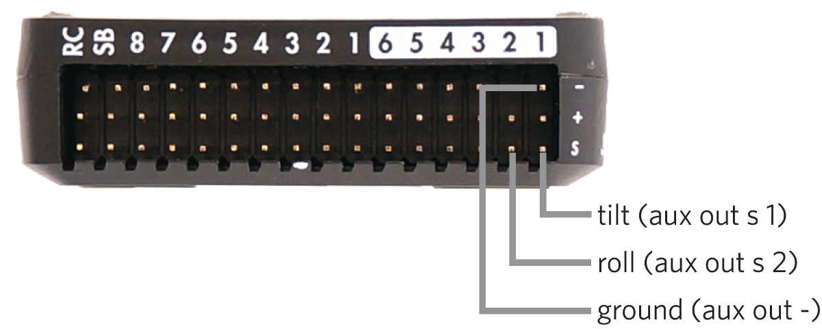
Connect the gimbal to Pixhawk’s auxiliary output pins. Connect tilt (pitch) to aux out signal (s) pin 1, roll to aux out signal (s) pin 2, and ground to an aux out ground (-) pin.

Gimbal configuration through the mission planner
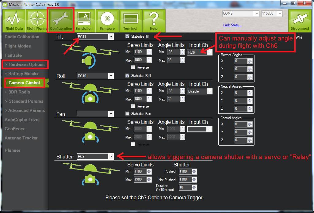
Under the configuration Menu, Hardware Options you will find a Camera Gimbal set-up screen. (see image below)
For each servo/axis of your camera gimbal select the appropriate servo channel and ensure the “Stabilise” checkbox is checked.
Note
Modern brushless gimbals (like the SToRM32) usually come with their own controllers that handle gimbal stabilisation. For those controllers the Stabilise checkbox must not be checked.
The Servo Limits should be adjusted to ensure the gimbal servos don’t bind.
The Angle Limits should correspond to the tilt angle of the gimbal itself at the servo limits. If you find during testing that your gimbal is not properly remaining stabilised (for example it’s over or undercorrecting as you tilt the copter), adjust the angle limits up or down slightly.
(These are not really ‘angle’ limits but how much the servo is commanded to move within the limits of the 60° most servos can move.
eg If set to -60/+60 the servo will reach -30°/+30° (its limit) when the ‘copter reaches -60°/+60°
If set to -15/+15 the servo will reach -30°/+30° (its limit) when the ‘copter reaches -15°/+15°)
“Retract Angles” refer to the position of the gimbal when the mount’s mode is “retracted” (i.e. MNT_MODE=0). “Retracted” normally means when the gimbal is pulled into the body of the aircraft which is generally not relevant for multicopters.
“Neutral Angles” refer to the position of the gimbal when the mount is first initialised. This is normally facing straight forward.
“Control Angles” are parameters to allow control of the gimbal from a ground station perhaps using a joystick. These values are overwritten by the ground station so there’s no point in updating them on the MP screen.
If you find your gimbal is moving in the wrong direction, check the Reverse checkbox.
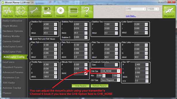
If you wish to adjust the gimbal tilt, roll or pan while flying, you can set the input channel to “RC6” which normally corresponds to your transmitters tuning knob.
Note
If you do this you need to set your CH6 Opt to CH6_NONE in the
Mission Planner Standard Parameters | Configuration screen.
Aligning Min and Max PWM values with full throw of gimbal
This section shows how to align the maximum and minimum PWM servo settings:
- Tilt airframe over hard left ( just past where the servo stops moving, or ~45 deg ), and raise the “Roll” “Servo” “Min” value until the servo starts to physically move a tiny bit, stop there.
- Tilt airframe over hard right ( just past where the servo stops moving, or ~45 deg ), and lower the “Roll” “Servo” “Max” value until the servo starts to physically move a tiny bit, stop there.
- Repeat for Pitch ( forward and backward motion)
Leveling/centering the gimbal
To level and centre the gimbal:
- Keep the airframe perfectly straight-and-level
- If the gimbal is not quite perfectly level, tweak the hardware first, eg, get servo horn/s so that gimbal is as close to level as possible before doing next step/s .. do this by unscrewing horn from servo and repositioning it, and/or if using push-rods to the gimbal, by adjusting the length of them).
- If “tilt” is still not quite level, you can “trim” it by adjusting the Tilt->Angle->Min and Tilt->Angle->Max … BOTH by one click in the same direction ( eg, click both down arrows once each) This will ensure that the difference between them remains constant ( important ), but will adjust the “centre” position of the gimbal by small amounts ( do not do this too much as it affects the maximum throw/s at the extremeties by the same amount).
Common fixes for poor video
Some of the more common causes and solutions for poor video are listed below:
- “Jello” effect (or rolling shutter) is a by-product of using a camera with a CMOS sensor (GoPro, et al) caused by vibration from unbalanced props/motors and can be mitigated by mounting the camera on soft rubber, silcone, foam ear plugs or sometimes just on velcro.
- digital and optical stabilization systems found in many cameras often
do not perform well because of the vibrations found on many
multicopters.
- Exceptions: the Sony video camera balanced steady shot system is very effective even at maximum 30 power zoom.
- If you have jerky camera movement adjust the RC_Feel parameter to a lower number such as 50 or 25.
- For better and smoother Yaw, use Expo control on your RC and lower the Acro_Yaw_P gain in APM.
It is important to remember that even with a perfect setup, photography is an art as well as a science. Using the camera pointing straight to ground is a good place to start, but more dramatic viewpoints can be achieved with angles other than vertical. Mount about 40 degrees deviation from vertical to obtain mainly ground photos but with oblique view. About 70 degrees off vertical will give you a lot more sky giving scenic photos (from Draganfly). ArduPilot will stabilise the gimbal to whatever position you set.
Shutter configuration
See Camera Shutter Configuration in Mission Planner for information on how to integrate shutter triggering with ArduPilot. Several (camera-specific) mechanisms for getting the trigger signal to the camera are discussed here.

