Relay Switch
A “Relay” is an digital output pin on the flight controller that can be switched between 0 volts and either 3.3V or 5V. Similar to a servo it allows the flight controller to invoke some action from another device on the vehicle. Up to 4 pins can be defined as relays in Copter, and 6 in Plane and Rover.
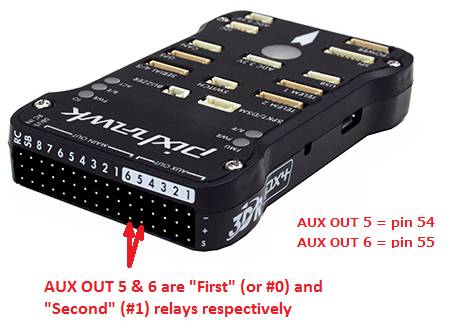
Relay pins on the Pixhawk
On the Pixhawk AUX OUT 5 (pin 54) and AUX OUT 6 (pin 55) are setup as the “First” (or #0) and “Second” (or #1) Relays respectively.

The number of available Relays can be increased to a maximum of 6 by reducing the number of AUX pins used as Servo outputs. This can be accomplished by reducing the BRD_PWM_COUNT from 4 to 2 or 0. Likewise, on other controllers, which have only PWM outputs, setting BRD_PWM_COUNT to a lower number will free up those outputs for use as GPIOs for controlling relays.
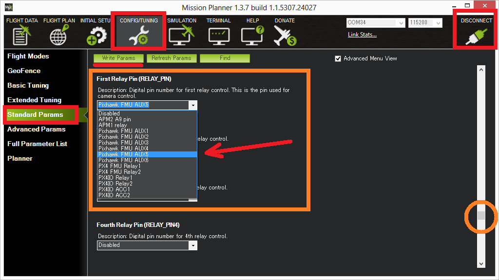
Defining the relay pins through the Mission Planner
The First ~ Fourth relay pins can be defined most easily using the Mission Planner’s Config/Tuning screen’s Standard Params list as shown below for the Pixhawk. For other boards, if you know the exactly pin number to use, the RELAY_PIN parameter can be set directly.
These are usually defined in the flight controller’s hwdef.dat file here .

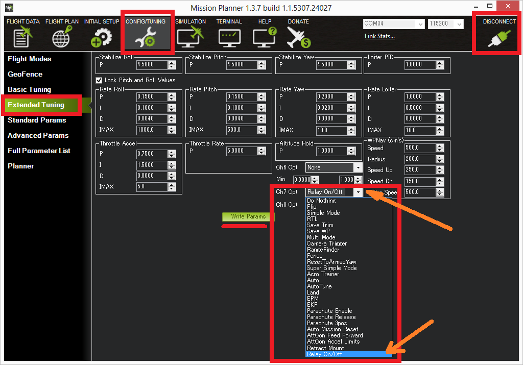
Pilot control of the relay
The relays can be controlled with the auxiliary switches. For Copter:

For Plane, setting the RCx_OPTION parameter, such as RC5_OPTION . For Rover, see Auxiliary Functions .
Mission control of the relay
Similar to a servo, the Relays can be activated during a mission using the Do-Set-Relay mission command. This is described on the Copter Mission Command List wiki page.