Common Power Module

Many flight controllers can be purchased with an analog power module that provides a stable power supply to the flight controller and also supports measuring the battery voltage and current consumption.
Specifications
Below are typical limits but it may be best to confirm directly with the vendor:
- Maximum input voltage of 18V (4S lipo)
- Maximum of 90 Amps (but only capable of measuring up to 60 Amps)
- Provides 5.37V and 2.25Amp power supply to the flight controller
Warning
The Power Module provides enough power for the flight controller, receiver, and a few low powered peripherals (lidar, telemetry) but does not have enough power for servos or high current devices like FPV transmitters or the RFD900 radios. More information on powering the Pixhawk can be found here
Connecting to the flight controller
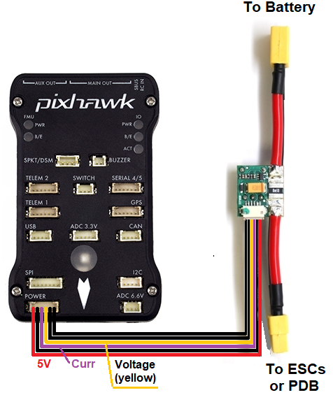
The 6 pin cable from the power module plugs into the POWER port of the flight controller

The battery is connected to the power module’s male connector. The ESC or Power Distribution Board should be connected to the power module’s female connector.
Configuration
Most ground stations provide a battery monitor interface but the parameters can also be set manually:
- BATT_MONITOR = 3 to measure only voltage or 4 to measure both voltage and current (you will need to reboot the board after changing this)
- BATT_VOLT_PIN = 2. The flight controller pin connected to the power module’s voltage pin
- BATT_VOLT_MULT converts the analog voltage received from the power module’s voltage pin to the battery’s voltage
- BATT_CURR_PIN = 3. The flight controller pin connected to the power module’s current pin
- BATT_AMP_PERVLT converts the analog voltage received from the power module’s current pin to the battery’s current
- BATT_AMP_OFFSET voltage offset received from the power module’s current pin when ther is no current being pulled from the battery
Instructions for setup and calibration using the Mission Planner can be found here A Blog post with instructions for set-up using QGC can be found here
Dual Battery Monitoring
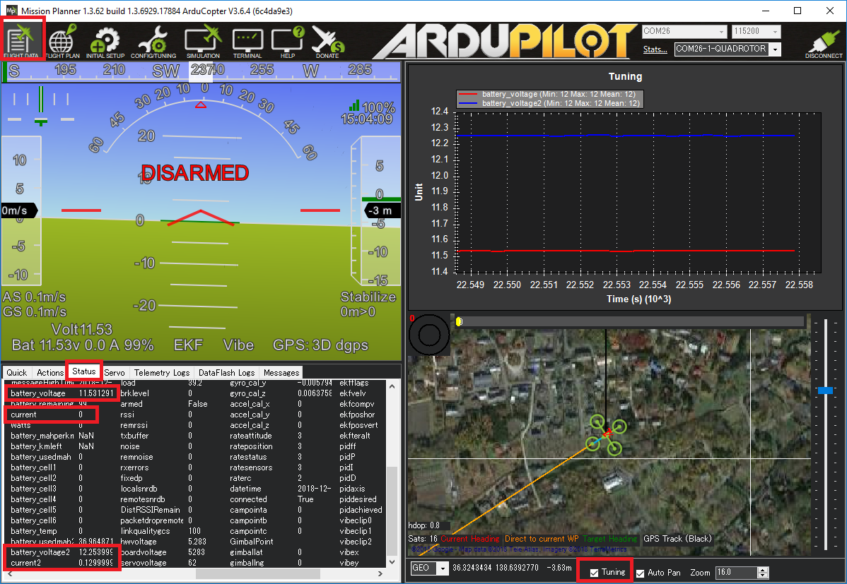
If the flight controller has additional analog-to-digital pins available, a second battery can be monitored by setting up the BATT2_ parameters. The values below allow reading a second battery’s voltage and current using The Cube’s POWER2 port.
- BATT2_MONITOR = 4 to measure both voltage and current (you will need to reboot the board after changing this)
- BATT2_VOLT_PIN = 13
- BATT_CURR_PIN = 14
The BATT2_VOLT_MULT and BATT2_AMP_PERVLT should also be set by comparing the reported values vs values collected using a hand held voltage meter

Failsafe
Instructions for battery failsafe can be found here