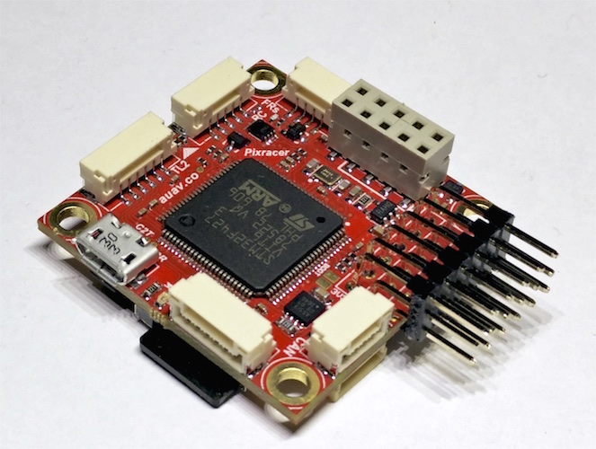
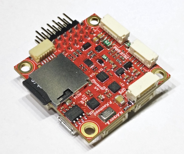
Pixracer
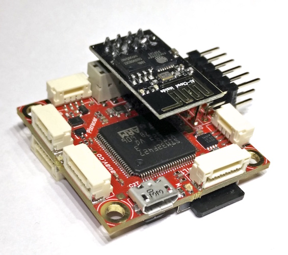
The Pixracer is the first autopilot of the FMUv4 Pixhawk generation. It comes with a small Wifi extension board.
Overview
The Pixracer is the common name for the FMUv4 generation of Pixhawk flight controllers. It has been designed primarily for the demanding requirements of small multicopters, but of course can be used on planes and other vehicles which require no more than 6 pwm outputs for controlling escs and motors. Pixracer is available from the mRobotics
Tip
At time of writing the autopilot is still being evolved/improved. The final version may very slightly from the information provided here.
This video below provides a detailed overview of the board. Additional information can be found on pixhawk.org and the mRobotics.
Specifications
- Processor:
- MCU - STM32F427VIT6 rev.3
- Ultra low noise LDOs for sensors and FMU
- FRAM - FM25V02-G
- Sensors
- Gyro/Accelerometer: Invensense MPU9250 Accel / Gyro / Mag (4 KHz)
- Gyro/Accelerometer: Invensense ICM-20608 Accel / Gyro (4 KHz)
- Barometer: MS5611
- Compass: Honeywell HMC5983 magnetometer with temperature compensation
- Power
- 5-5.5VDC from USB or PowerBrick connector. Optional/recommended ACSP4 +5V/+12V Power Supply.
- Interfaces/Connectivity
- Wifi: ESP-01 802.11bgn Flashed with MavESP8266
- MicroSD card reader
- Micro USB
- RGB LED
- GPS (serial + I2C)
- TELEM1/TELEM2
- Wifi serial
- FrSky Telemetry serial
- Debug connector (serial + SWD)
- Connectors: GPS+I2C, RC-IN, PPM-IN, RSSI, SBus-IN, Spektrum-IN, USART3 (TxD, RxD, CTS, RTS), USART2 (TxD, RxD, CTS, RTS), FRSky-IN, FRSky-OUT, CAN, USART8 (TxD, RxD), ESP8266 (full set), SERVO1-SERVO6, USART7 (TxD, RxD), JTAG (SWDIO, SWCLK), POWER-BRICK (VDD, Voltage, Current, GND), BUZZER-LED_BUTTON.
- Dimensions
- Weight ?
- 36 x 36mm with 30.5 x 30.5mm hole grid with 3.2mm holes
Connector pin assignments
Unless noted otherwise all connectors are JST GH
TELEM1, TELEM2+OSD ports
| Pin | Signal | Volt |
|---|---|---|
| 1 (red) | VCC | +5V |
| 2 (blk) | TX (OUT) | +3.3V |
| 3 (blk) | RX (IN) | +3.3V |
| 4 (blk) | CTS (IN) | +3.3V |
| 5 (blk) | RTS (OUT) | +3.3V |
| 6 (blk) | GND | GND |
GPS port
| PIN | SIGNAL | VOLT |
|---|---|---|
| 1 (red) | VCC | +5V |
| 2 (blk) | TX (OUT) | +3.3V |
| 3 (blk) | RX (IN) | +3.3V |
| 4 (blk) | I2C1 SCL | +3.3V |
| 5 (blk) | I2C1 SDA | +3.3V |
| 6 (blk) | GND | GND |
FrSky Telemetry / SERIAL4
| PIN | SIGNAL | VOLT |
|---|---|---|
| 1 (red) | VCC | +5V |
| 2 (blk) | TX (OUT) | +3.3V |
| 3 (blk) | RX (IN) | +3.3V |
| 4 (blk) | GND | GND |
RC Input (accepts PPM / S.BUS / Spektrum / SUMD / ST24)
| PIN | SIGNAL | VOLT |
|---|---|---|
| 1 (red) | VCC | +5V |
| 2 (blk) | RC IN | +3.3V |
| 3 (blk) | RSSI IN | +3.3V |
| 4 (blk) | VDD 3V3 | +3.3V |
| 5 (blk) | GND | GND |
CAN
| PIN | SIGNAL | VOLT |
|---|---|---|
| 1 (red) | VCC | +5V |
| 2 (blk) | CAN_H | +12V |
| 3 (blk) | CAN_L | +12V |
| 4 (blk) | GND | GND |
Power
| PIN | SIGNAL | VOLT |
|---|---|---|
| 1 (red) | VCC | +5V |
| 2 (blk) | VCC | +5V |
| 3 (blk) | CURRENT | +3.3V |
| 4 (blk) | VOLTAGE | +3.3V |
| 5 (blk) | GND | GND |
| 6 (blk) | GND | GND |
Switch
| PIN | SIGNAL | VOLT |
|---|---|---|
| 1 (red) | SAFETY | GND |
| 2 (blk) | !IO_LED_SAFETY | GND |
| 3 (blk) | CURRENT | +3.3V |
| 4 (blk) | BUZZER- | - |
| 5 (blk) | BUZZER+ | - |
Debug port (JST SM06B connector)
| PIN | SIGNAL | VOLT |
|---|---|---|
| 1 (red) | VCC TARGET SHIFT | +3.3V |
| 2 (blk) | CONSOLE TX (OUT) | +3.3V |
| 3 (blk) | CONSOLE RX (IN) | +3.3V |
| 4 (blk) | SWDIO | +3.3V |
| 5 (blk) | SWCLK | +3.3V |
| 6 (blk) | GND | GND |
Where to Buy
See also
Note
Some information and images in this page were copied from pixhawk.org, docs.px4.io and the mRobotics shop


