Archived: Installing the PX4FMU on a QuadCopter
Warning
ARCHIVED ARTICLE
This article is for creating a quadcopter using the PX4FMU only, which is one approach for creating a very small autopilot. Arsovtech have created a small Pixhawk based board that is much more popular with the community.
Overview
Bill Of Materials:
- Copter firmware version 3.1 and later supports only the combined system of the PX4 FMU and PX4 IO board; the FMU-only system is no longer supported. Purchase a PX4 FMU kit from 3DRobotics LINK_BROKEN and a PX4 I/O board LINK_BROKEN
- A special cable that fits into the PX4’s main “Multi” connector will allow you to perform the primary wiring and it is available from 3DRobotics LINK_BROKEN
- If you choose, you can cut off the single pin connectors and solder directly to the necessary locations and trim back the excess wires.
- Use the 4 supplied nylon standoffs to mount the PX4FMU to a piece of
scrap plastic or fiberglass sheet the same size as the FMU.
- Mount the board to your copter with four 3/4” squares of Kyosho Zeal gel or double sided foam tape to provide vibration isolation.
Mount your PX4-FMU board in a central location on top of your QuadCopter.
- The PX4FMU board Normally has the SD card on top.
- It can sometimes be advantageous to mount the PX4FMU with the other side up for better LED observation.
- If you do mount the PX4FMU board with the Component side up it will be necessary to set the “Board Orientation (AHRS_ORIENTATION)” parameter to “Roll 180” in the Advanced Parameter List in Mission Planner.
- The arrow labeled “FRONT” should be facing to the front of the aircraft (also the large black board interconnect connector).
- If you use the vibration dampers suggested above it is best to put a small O-ring on top of the damper and under the PX4 Board before fastening it “gently” down with the supplied nuts to prevent damage to the board.
- In fact, these dampers may not provide adequate damping and you should review the Wiki section on vibration control.
Mount the GPS facing up with an unobstructed “view” of the sky.
- The GPS can be mounted on a short riser to give it the widest satellite access.
PX4-FMU Only Wiring Diagram for QuadCopters using a PPM-SUM receiver
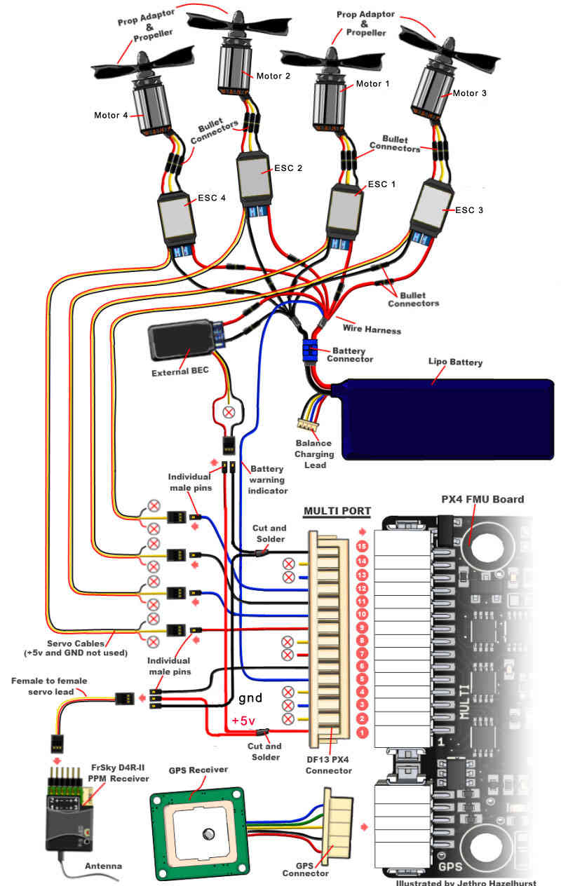
Wiring the PX4FMU Board to Your QuadCopter
- Use heavy gauge wire to interconnect the ESC’s Ground and power
leads to a Battery Connector.
- A Power Distribution board can also be used.
- Connect your BEC (5 volt power supply) power in leads to the battery input leads.
- Connect the the BEC Ground output to the PX4’s Ground (Multi connector pin 15).
- Connect the BEC Power output to the PX4’s power In (Multi connector pin 1).
- NOTE! Instead of a separate BEC as shown, the power and ground leads (signal side) from one of your ESCs that contains a BEC can be wired to the Multi connectors pins 1 and 15 to provide PX4 board power.
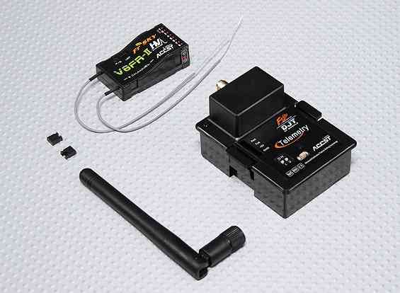
- The PPM-SUM receiver may be wired with a connecting cable as shown
in the diagram above.
- Or the PPM-SUM signal and power and ground leads from the 15 pin DF13 “Multi” connector may be directly wired to a 3 pin servo/receiver connector.
- Connect your PPM-Sum RC receivers signal wire to pin 6 of the Multi connector on the PX4 board.
- Connect the PPM-SUM RC Receivers Ground lead to pin 15 of the Multi connector on the PX4 board.
- Connect the PPM-SUM RC Receivers Power lead to pin 1 of the Multi connector on the PX4 board.
- Wire the PX4FMU board’s 4 servo out signals to the ESC control
inputs.
- The wires can be put together with connectors as shown in the diagram or solder and heat shrink tubing can be used.
- Wire PX4FMU PWM control 4 (Multi Connector pin 9) to The ESC signal in for Motor 4.
- Wire PX4FMU PWM control 2 (Multi Connector pin 10) to The ESC signal in for Motor 2.
- Wire PX4FMU PWM control 1 (Multi Connector pin 11) to The ESC signal in for Motor 1.
- Wire PX4FMU PWM control 3 (Multi Connector pin 12) to The ESC signal in for Motor 3.
- Run a wire from the PX4FMU’s Battery Monitor connection (Multi Connector pin 5) to the positive battery power lead.
- Note! The cable that is supplied in the plastic envelope with the
UBLOX GPS which has white 6 pin connectors on both ends is NOT the
correct cable for the PX4.
- The correct longer cable is provided in a separate envelope and has a 5 pin “beige” connector on one end and a 6 pin white connector on the other end.
- Plug the correct GPS cable’s white 6 pin connector into the 6 pin socket on the GPS.
- Plug the beige 5 pin connector into the PX4’s 5 pin GPS socket which is next to the 15 pin DF13 Mini connector.
- Plug the 2 pin connector attached to the lead supplied with the buzzer into the buzzer socket on the side of the PX4FMU board that has the SD card holder on it.
- In Mission Planner in the Complete Parameter List it will be
necessary for you to set the BRD_SAFETYENABLE parameter to 0 =
off.
- This is because the safety switch connects to the IO board’s on board microcontroller and there is no switch for the PX4FMU only.
PX4-FMU Only Wiring Schematic for QuadCopters using a PPM-SUM receiver
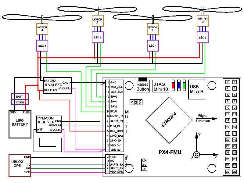
Wiring your Motors for X or + mode configuration
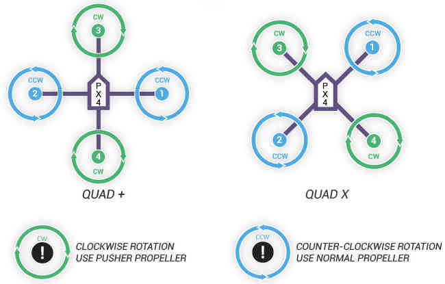
Using a Standard RC Radio Receiver with an 8 channel PPM Encoder
- You can use a standard radio receiver with an 8 channel PPM Encoder
in place of the PPM-SUM receiver.
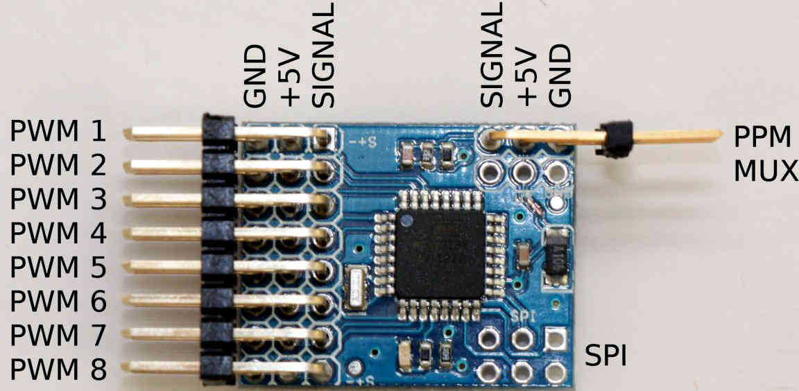
- An 8 Channel PPM Encoder is available from jDrones here.
- Solder a 3x8 Right angle connector from the top into one end of the 8 Channel PPM Encoder board.
- With the 3x8 connector up and facing away from you, solder a 3x1 Right angle connector on the right edge of the 8 Channel PPM Encoder board.
- Connect 5-8 output channels of your receiver to the inputs of the 8
Channel Encoder (signal wire furthest from board) with 5-8 female to
female servo jumpers.
- Connect the PPM-SUM signal output of the Encoder to the PX4FMU boards PPM sum signal input (Pin 6 of the 15 pin Multi connector).
- Connect the PPM-SUM ground input of the Encoder to the PX4FMU boards ground connection (Pin 1 of the 15 pin Multi connector).
- Connect the PPM-SUM power input of the Encoder to the PX4FMU boards power connection (Pin 15 of the 15 pin Multi connector).
3DRobotics 8 Channel PPM-Sum Encoder
