Archived: Hoverthings Flip Sport Quadcopter
Warning
ARCHIVED ARTICLE
The frame is no longer in production/available for purchase. Some of the instructions cover PX4FMU/PX4IO, which is no longer supported.
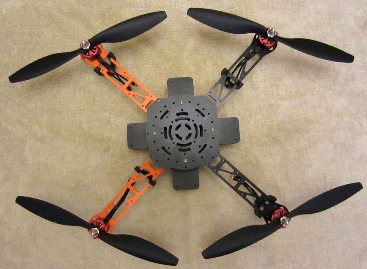
The Hoverthings FLIP Sport is very easy to build resulting in a remarkably sturdy and very high performance little quadcopter. The FLIP Sport is well suited to FPV and GoPro photography and videography and can even incorporate a brushless gimbal.
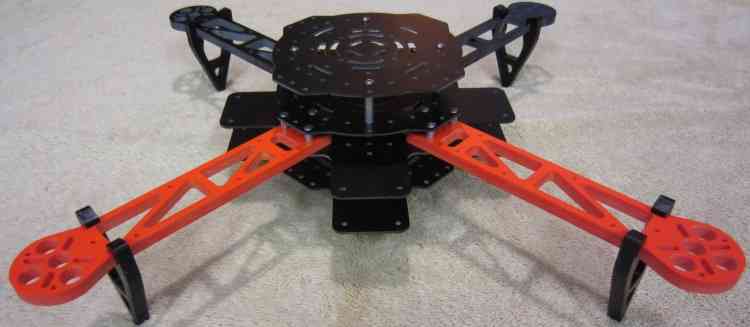
Why a FLIP Sport?
- The easiest inexpensive high quality build your own project is either the F330 or 450 DJI FlameWheel QuadCopter.
- The F330 build is detailed elsewhere and the F450 is pretty much identical.
- I really love those little FlameWheels for delivering many hours of fun and resisting my every effort to destroy them.
- This time I thought I’d try and kick it up a notch, something even more indestructible and maybe even more fun.
- The Flip frame kit is $89.00 from Hoverthings.
- In addition to the standard Sport frame kit I also purchased an extended tab pair of center frame pieces and some extra 7/8” stand offs.
- It is billed as being nearly indestructible and short of direct Nuclear blast effects, they are probably right.
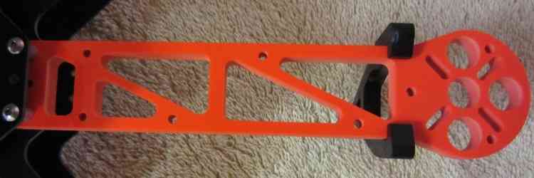
- The frame arms on these Flips are billed as being incredibly stiff and incredibly strong.
- The arms are CNC milled high density 1/4” thick fiberglass and are very stiff, they should be able to withstand a lot of punishment.
- The frame centers are also very strong and stiff fiberglass and it it seems likely all of it is G10.
- This is a small 380 size frame and will accommodate 10” propellers (Right between the Flamewheel F330 and F450.)
What to get
A Hoverthings Flip Sport Frame (approx $89.00 USD).
Two tabbed center sections and eight 7/8” standoffs (e.g. similar to these).
Four DJI motors for Flamewheel from Amain Hobby for $24.00 each.
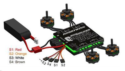
A 20 or 25 Amp four in one ESC from Off the Grid Water for $40.00.
A Pixhawk compatible flight controller.
A GPS and Compass Module module.
Two normal and two reverse rotation DJI compatible Gemfan 10” carbon filled propellers from RC Dude.
A 2600 to 4000mah LiPo battery that fits between the 2 bottom plates.
PPM-Sum compatible receiver that works with your RC transmitter: FRSky(Delta 8), Futaba SBus or Spektrum satellite recommended.
For a PX4 system: A Pad of Kyousho Zeal Antivibration gel and four nylon or aluminum 1 1/2” threaded standoffs.
Assembling the frame
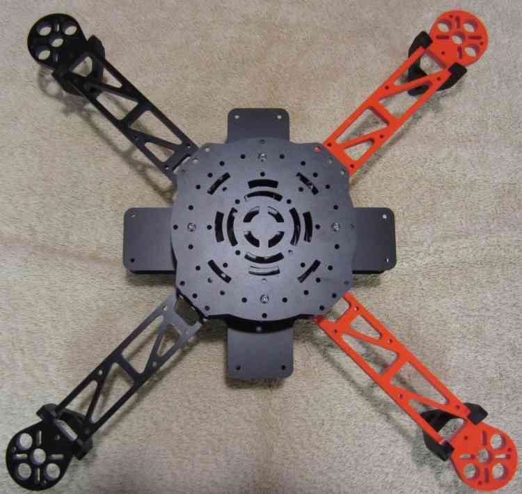
- There are two different construction methods depending on whether you are using a Pixhawk or a PX4FMU/PX4IO.
- For the Pixhawk you will use the second untabbed center plate on top as shown above, for a PX4FMU/PX4IO you will not.
- Construction procedure is as follows (Use blue Locktite on all machine screws.)
- Assemble the 2 tabbed center sections with four 7/8” standoffs on the 2 holes an inch apart 2” in from the end on 2 opposing sides.
- Mount the arms to the top of one of the tabbed center frames using
the short standoffs above the arm and use locktite.
- Ensure that the standoffs mounting the two tabbed frame sections are on either side of your copter, not front to back.
- Put the longer screws up through the tabbed plate and arms (2 on the outside 1 in the middle towards the middle) into the short standoffs.
- Insert and your four in one ESC in between the arms with the excess
Motor wire wrapped around the ESC
- Leave about 3 inches of the 3 ESC motor wires sticking out under each arm (I also braided each motors wires on mine.)
- Leave the ESC signal wires and power leads sticking out the back (between the 2 black arms on mine.).
- Put an untabbed frame plate on top of your frame and secure with 12 screws to the top of the standoffs.
- Install your DJI motors onto the frame arms with the supplied screws (use Locktite) with the motor wires facing the copter.
- Thread the motor wires through the top frame arm opening and connect to the ESC wires (tuck excess lead into frame).
Installing the Pixhawk flight controller
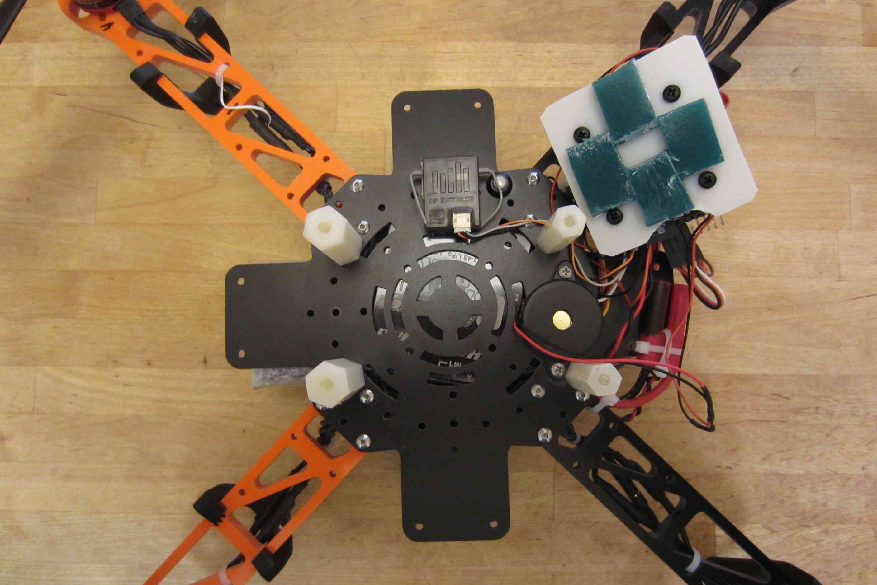
- If you are using a Pixhawk, mount the 4 remaining 7/8” long standoffs, directly over the ones securing the bottom frame plates.
- Place a 1” square of the Double-sided foam tape that came with the Pixhawk on the bottom of it at each corner.
- Adhere the Pixhawk to the top of the frame with the arrow pointing to the front (between the 2 orange arms on mine).
- Drill a hole through the top 2 frame plates near a frame arm near the edge on one side to accommodate the “safety” button.
- Also mount the buzzer on the top frame member on one side where it will not interfere with a receiver installation.
- Connect the 3DR power module to the Pixhawk connector and attach the power module out of the way also.
- Solder the other end of the power module wires into a battery connector along with the ESC battery leads.
- Install the ESC’s signal leads into the Pixhawk (Main Out) servo
connectors (signal wire on top).
- Red wire into 1, Orange into 2, White into 3 (with red and black below) and Brown into 4.
- Install the GPS and compass wires into the GPS/Compass module and the Pixhawk.
- Mount your receiver with double sided tape or Velcro on the top frame
member to one side of (and not touching) the Pixhawk.
- Run a single servo lead from the PPM-Sum output of the receiver to the left side (RC) input of the Pixhawk.
- Or if it is a Spektrum Satellite run the Spektrum receiver lead to the Spektrum socket on top of the Pixhawk.
- Mount the top untabbed frame member over the Pixhawk to the 7/8” standoffs you already installed above.
- Mount the GPS module to the top center of the top frame plate using double sided tape.
Installing the PX4FMU/PX4IO flight controller
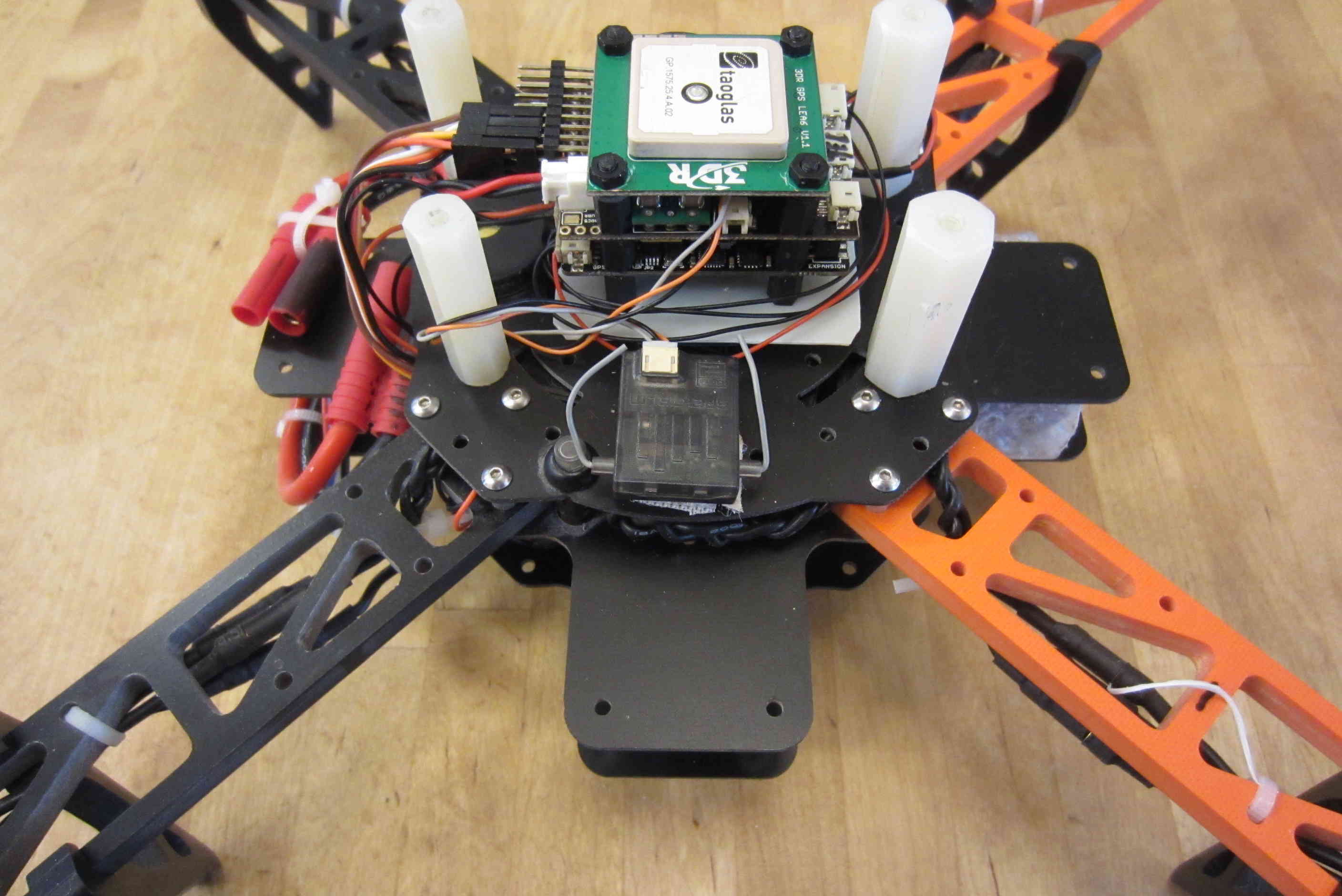
- If you are using a PX4 we can’t use the top frame plate but can construct a little hard top if desired.
- Cut a 2” by 2” rectangle from scrap plastic or fiberglass to support the PX4FMU/PX4IO.
- Drill 4 holes in the rectangle that line up with the mounting hole in the PX4 board (roughly centered)
- using 4 of the supplied black screws, mount 4 standoffs to the rectangle.
- Insert the PX4FMU board (connector side up) over the 4 standoff studs and (carefully) screw 4 more standoffs over them.
- Carefully fasten 4 nuts over the exposed studs securing the PX4FMU/PX4IO modules to the rectangle you made.
- Place the PX4IO board over the PX4FMU board so that the connector is aligned and push down over the studs.
- Place a 3/4” square piece of the Kyosho zeal at each edge of the “rectangle” between the standoff screws.
- Adhere the rectangle to the center of the top of the frame with the servo connector facing to the rear (between the black frame arms).
- Drill a hole through the top 2 frame plates near a frame arm near the edge on one side to accommodate the “safety” button.
- Also mount the buzzer on the top frame member behind the PX4FMU/PX4IO stack such that it does not touch the “rectangle”.
- Insert the power connector into the PX4IO board and solder the power leads and the ESC power leads to a battery connector.
- Connect the buzzer and “Safety” button leads to the PX4FMU/PX4IO boards.
- Install the ESC’s signal leads into the PX4IO board servo connectors (signal wire on top).
- Red wire = right pins, Orange = 2nd from right, White = 3rd from right (with red and black below) and Brown = 4 from right.
- Mount your receiver with double sided tape or Velcro on the top frame
member to one side of (and not touching) the “rectangle”.
- Ensure that your receiver does not block the USB connector on the side of the PX4FMU board (put it on the other side).
- Run a single servo lead from the PPM-Sum output of the receiver to the far left side of the PX4IO servo connector.
- Or if it is a Spektrum Satellite receiver run the Spektrum receiver lead to the Spektrum socket on top of the Pixhawk.
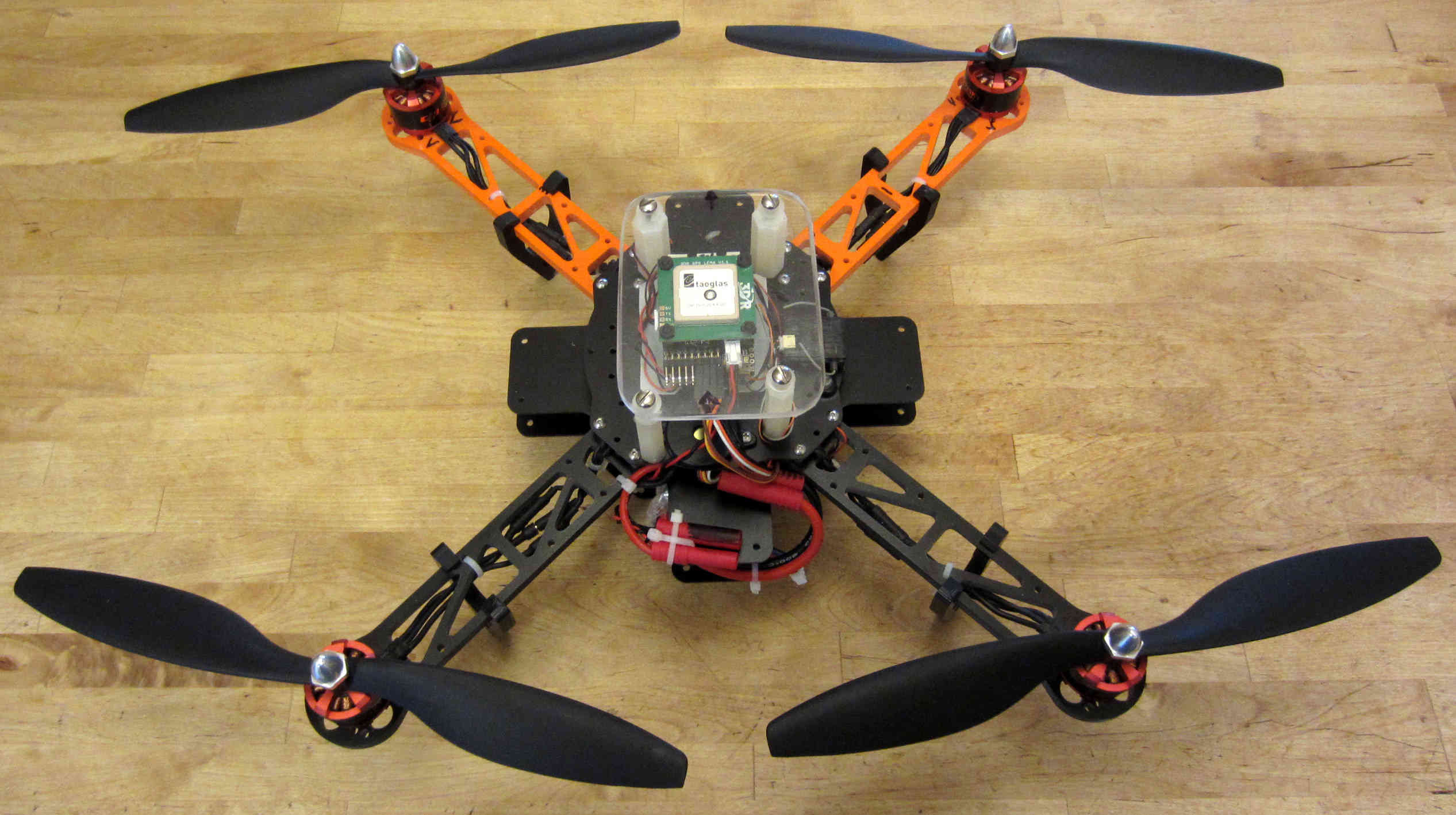
- To use the remaining frame plate as a top cover screw the 4 standoffs
to the top of the frame using existing holes near the edge.
- Screw the plate to the 4 standoffs.
- You can make your own top cover from a rectangle of plastic or
fiberglass (I used Plexiglass, transparent is useful).
- Ensure that the rectangle is of appropriate size and shape to permit you to secure the standoffs to the top plate.
- Drill holes in the rectangle at the appropriate locations and if needed into the top frame member as well.
- Attach the standoffs to the top frame member and to the Rectangular top you have made.
- Adhere the GPS/Compass module to the center of the top of the top
cover (it doesn’t matter which way it is facing).
- Connect the GPS / Compass module to the PX4IO with the supplied wiring cables.
- Note my setup uses an older style UBlox standalone GPS which I have mounted directly to the PX4 stack.
Final assembly
- Mount the battery between the lower frame sections and secure it with a Velcro strap inserted through the bottom frame plate slots.
- Route and secure the wires and cables with Zip Ties as shown to prevent snagging on the propellers or anything else.
- Ensure that the battery cable is secure but accessible to be plugged in when needed.
Setup and additions
- Your Flip can now be configured as described elsewhere in this wiki for Pixhawk.
- There is space for a 3DR telemetry radio and / or an OSD and FPV
transmitter between the 2 side tabs.
- An FPV camera may easily be mounted in front of the battery between the 2 front tabs.
- If you use FPV keep it’s transmitter and antenna well away from the GPS.
- The Flip has more than adequate power to support a GoPro camera with a brushless gimbal and the necessary extended landing gear.
- I have had several crashes and only managed to break 2 props while trying (unsuccessfully) to cut down a 80’ bull pine tree with them.
- This little copter is very high performance, fully acrobatic, surprisingly efficient and nearly indestructible and it is a blast to fly.